
General Purpose Registers
There are 8 general purpose registers in 32-bit mode:
- accumulator register EAX. Used in arithmetic operations
- base register EBX. Used as pointer to data in the DS segment
- counter register ECX. Used in shift/rotate instructions and loops
- data register EDX. Used in arithmetic operations and I/O operations
- stack pointer register ESP. Used as pointer to the top of the stack
- stack base pointer register EBP. Used to point to the base of the stack
- source index pointer ESI. Used as a pointer to a source in stream operations
- destination index register EDI. Used as a pointer to a destination in stream operations
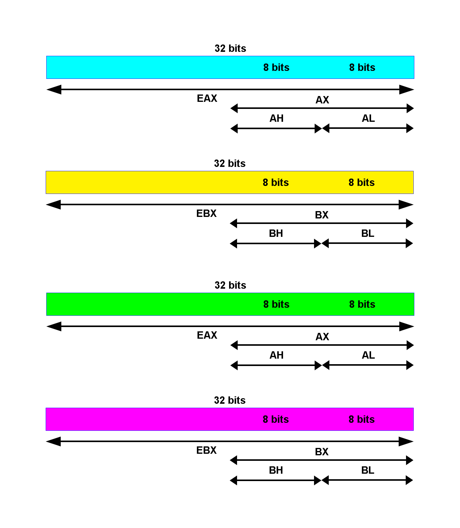
Register EAX, EBX, ECX, and EDX can be accessed in 16-bit mode:
- AX
- BX
- CX
- DX
It also can be accessed in 8-bit mode:
- the least significant byte (LSB) or low half of AX is AL and the most significant byte (MSB) or high half of AX is AH
- the least significant byte (LSB) or low half of BX is BL and the most significant byte (MSB) or high half of BX is BH
- the least significant byte (LSB) or low half of CX is CL and the most significant byte (MSB) or high half of CX is CH
- the least significant byte (LSB) or low half of DX is DL and the most significant byte (MSB) or high half of DX is DH
Segment Registers
Segment registers are 16-bit registers. They are 6 segment registers:
- Stack Segment (SS). Pointer to the stack
- Code Segment (CS). Pointer to the code
- Data Segment (DS). Pointer to the data
- Extra Segment (ES). Pointer to extra data (‘E’ stands for ‘Extra’)
- F Segment (FS). Pointer to more extra data (‘F’ comes after ‘E’)
- G Segment (GS). Pointer to still more extra data (‘G’ comes after ‘F’)
Segment registers are used to access memory segments. Memory segmentation is the old way of accessing memory regions. All major operating systems including OSX, Linux, (from version 0.1) and Windows (from NT) are now using paging.
EFLAGS Register
The EFLAGS is a 32-bit register used as a collection of bits representing Boolean values to store the results of operations and the state of the processor.
The 32-bit EFLAGS register contains a group of status flags, a control flag, and a group of system flags.
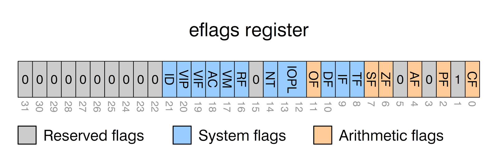
The status flags (bits 0, 2, 4, 6, 7, and 11) of the EFLAGS register indicate the results of arithmetic instructions, such as the ADD, SUB, MUL, and DIV instructions. The status flag functions are:
- Carry flag CF (bit 0), set if arithmetic operation generates a carry or a borrow out of the most significant bit of the result. This flag indicates an overflow condition for unsigned-integer arithmetic.
- Parity flag PF (bit 2), set if the least significant byte of the result contains an even number of 1 bits
- Auxiliary Carry flag AF (bit 4), set if an arithmetic generates a carry or a borrow out of bit 3 of the result. This flag is used in binary-coded decimal (BCD) arithmetic
- Zero flag ZF (bit 6), set if the result is zero
- Sign flag SF (bit 7), set equal to the most-significant bit of the result, which is the sign bit of a signed integer (0 indicates a positive value and 1 indicates a negative value)
- Overflow flag OF (bit 11), set if the integer result is too large a positive number or to small a negative number to fit in the destination operand
The control flag of the EFLAGS register controls the string instructions (MOVS, CMPS, SCAS, LODS, and STOS)
- Direction flag DF (bit 10), setting the DF flag causes the string instructions to auto-decrement (to process strings from high addresses to low addresses). Clearing the flag causes the string instructions to auto-increment (to process strings from low addresses to high addresses). The STD and CLD instructions set and clear the DF flag, respectively.
The system flags and IOPL field in the EFLAGS register control operating system or executive operations. They should not be modified by application programs. The functions of the system flags are as follow
- Trap flag TF (bit 8), set to enable single-step mode for debugging
- Interrupt enable flag IF (bit 9), controls the response of the processor to maskable interrupt requests. Set to respond to maskable interrupts; cleared to inhibit maskable interrupts
- Nested task flag NT (bit 14), controls the chaining of interrupted and called tasks. Set when the current task is linked to the previously executed task; cleared when the current task is not linked to another task
- I/O privilege level field IOPL (bit 12 and 13), indicates the I/O privilege level of the currently running program or task. The current privilege level (CPL) of the currently running program or task must be less than or equal to the I/O privilege level to access the I/O address space. The POPF and IRET instructions can modify this field only when operating at a CPL of 0
- Resume flag RF (bit 16), controls the processor’s response to debug exceptions
- Virtual-8086 mode flag VM (bit 17), set to enable virtual-8086 mode; clear to return to protected mode without virtual-8086 mode semantics
- Alignment check (or access control) flag AC (bit 18), if the AM bit is set in the CR0 register, alignment checking of user-mode data accesses is enabled if and only if this flag is 1. If the SMAP bit is set in the CR4 register, explicit supervisor-mode data accesses to user-mode pages are allowed if and only if this bit is 1
- Virtual interrupt flag VIF (bit 19), virtual image of the IF flag. Used in conjunction with the VIP flag. To use this flag and the VIP flag the virtual mode extensions are enabled by setting the VME flag in control register CR4.
- Virtual interrupt pending flag VIP (bit 20), set to indicate an interrupt is pending; clear when no interrupt is pending. Used in conjunction with the VIF flag
- Identification flag ID (bit 21), the ability of a program to set or clear this flag indicates support for the CPUID instruction
Instruction Pointer Register
The EIP register contains the address of the next instruction to be executed if no branching is done. EIP
can only be read through the stack after a call instruction.